Specs:
Overall height: 28"
Top: 18" x 18"
Apron width: 14"
Apron height: 4"
Legs: 1.25" taper to .75"
The legs are mortised with 3/8" tenons and pinned with 1/4" dowels. 3/4" thick top, edged glued from 3 boards, hand planed and scraped flat. The bottom side of the top has 1/4" deep, by 2" long bevel, leaving a 1/2" thick edge. Finish is a seal coat of thinned shellac topped with multiple coats of danish oil. The top surface was wet-sanded with 320 grit and oil to fill grain pores.
A new CNC has been taking shape in my shop over the last several months. It's a major rebuild of my previous router-lathe that adds another axis of movement and a lot more capability. I kept quiet about it until it was actually running because the design is a little unusual and I wasn't entirely sure if it was going to work -- I wanted to avoid having to say "that new machine I'm building? umm, never mind...".
It's still under construction, but far enough along that I can use it to make parts for itself.
Configured for flat work
Configured for 4th axis (lathe)
It's basically a standard 3-axis router built around an old 11" x 36" wood lathe. It has two configurations: a 3 axis router, or remove the table to access the lathe for 4th axis work. As with previous projects, most of the design work was done in Sketchup before and during construction.
Configured for rotary work on the lathe
With the table installed for flat work.
Here are the first cuts:
Rotary axis test.
The rotary axis (lathe) drive. 16:1 ratio -- kevlar belts.
I'm working with friend on a wind-powered kinetic sculpture. This is a half-scale model out of wood to verify the mechanics.
And here's a road test with the sail attached. I'm calling out engine RPM to estimate speed because the speedometer is not very accurate at low speeds. 1900 rpm equals somewhere between 9 & 10 mph.
This test provided great information about how it behaves in the wind. We're going to try less offset on the crankarm and reduce the amount of travel in the rods. Oh, and make it stronger, too.
Here's a wood sign I made for a friend's woodworking shop, Artsubstrates. This is the first time I've wrapped a 3D shape around the rotary axis. It worked better than expected.
(note: from here on is going to be pretty dull for anyone not building a cnc machine. ...and maybe for those who do, as well.)
I generated the text using "FEngrave" a great piece of software for generating gcode for signs. It does one thing and does it very well. Highly recommended. Then I used another piece of software to take the output from FEngrave and wrap it around the rotary axis.
Recent upgrades:
Some upgrades were required to convert from arduino 2 axis
control to 3 axis CNC. Added was new z axis assembly with stepper motor and controller, new belts and pulleys on the rotary axis to increase the
gear ratio, and limit switches on the linear axes.
New Z axis assembly with motor.
The new Z axis assembly has 3/8" aluminum plate for the base and the
carriage platform, 5/8" O1 tool steel rods for rails and UHMW bearings
to slide on. I made another UHMW nut and used the acme threaded rod left over from the X axis. I'll have to re-think the UHMW bearing though -- they slide really smoothly by themselves but take a lot of adjustment to get the carriage to slide without binding with all 4 attached.
Limit switches on Z axis
Motor and switch wiring
Showing the limit switches and motor wiring on the Z axis. I used
ethernet cable and jacks for the limit switches, and heavier 22g wire
for the motor.
New rotary axis belts
The big automobile timing belt and diy pulley were replaced two XL timing belts and pulleys. increases the motor/ axis ratio from the previous 4:1 to 16:1. This provides a lot more holding power against the router and gives smoother rotary axis travel and much finer resolution. With the old belt, there was more backlash that I liked and at larger diameters, one step on the motor translated into as much as .003" of travel. With the new belts and gear reduction, resolution at large diameters is still very fine and I see less chatter during heavy cuts.
The current belts are neoprene with polyester fibers, which do stretch a little and is more noticeable with the double gear reduction. I purchased new belts with kevlar fibers that have very little stretch, but haven't installed them yet.
All this is because these 285 oz/in motors are OK for the two linear axis, but a bit puny
for the rotary axis. A motor upgrade on the rotary axis may be in order,
but would require a bigger power supply and new controller as well -- not in the current budget.
Wiring to the electronics enclosure. 5 pin XLR connectors with 22g stranded cable for the motors and ethernet cable and jacks for the limit switches and e-stop button. There's a vented cover for this enclosure, but after an overheating incident where the cooling fan lost power and the controllers started making real funny noises and smelling bad, I don't have the courage to close it up yet. I'm thinking of putting in a temperature monitor, but that may be overkill.
A lot has happened on the router lathe and this posting is way overdue. It's gained a nice new 3rd axis carriage driven by a stepper motor, adding programmable z-axis (depth of cut) control, and has been converted from arduino control to full CNC, controlled by a PC running Mach3. Here's a video of the first major part cut on the machine since the rebuild.
The conversion to a CNC controller opens up huge potential. The arduino was great for spirals, but it took a lot of code to generate them. I found I could do in 3 0r 4 lines of g code what took 100+ lines of arduino code. I could have installed Grbl and continued using the arduino as the CNC controller, but I like the feedback graphical programs like Mach3 and EMC2 provide. Although I do have an idea for a little internal thread-cutting machine that Grbl might be perfect for.
Cutting the square profile proved to be a bit of a challenge. Unfortunately, on this machine there's no way to move the cutter relative to the center line of the part (bad planning!), so cutting a flat is a little more complicated. After a calling up some forgotten math and doing some sloppy Excel scripting, I was able to make a spreadsheet to generate code to control depth of cut / rotation ratio that generates a flat surface as the part rotates. Then, rotating the part by increments between each cut to produce the spiral was a matter of learning how to use parameters and subroutines in g code to create loops
Here's the Excel function to make the square: =((Offset/COS(angle))+(tool_radius/COS(angle)))-tool_radius
...where offset is the distance from the center of the part to the flat surface you want to generate, angle is the angle relative to the axis of the cutter and tool_radius is... well tool radius. I have a spreadsheet that does all the math and generates g code for different angles and offsets. I'd be happy to share if anyone's interested, but I don't want to post it in its current unfinished state.
I've been salvaging old douglas fir beams from building demolitions for carving. Douglas fir takes on
this wonderful texture when it gets old: it becomes more consistent,
less difference in hardness between the rings, and it's easier to carve
across the grain than new fir. With a sharp chisel, you can make big,
bold cuts. Very satisfying. These two mobius carvings were early projects from reclaimed fir.
First attempt -- about 6"
It was a bit tough to visualize how the surfaces wrapped around the shape, so I started with models. First, I made a donut from modeling clay, drew the corners as they wrapped around the shape, and then scraped a flat plane between the lines. Next, I built a series of models in Sketchup -- a bit laborious, but it helped a lot to see what needed to be done.
To make the small mobius, I started with a donut with a round cross-section, traced the corners as they wrapped around the part and carved a flat surface between the lines, being careful to measure the flats radially. The larger one was harder: I made it in two halves, doweled together. The majority of the shaping was performed on each half separately, then the finish work was done with the part glued together.
A friend gave me some old fir boards torn out of her attic. They were getting in the way where I stacked them in the shop, so I decided to mill them down before storing them. But once I started cutting, I got a little carried away and made a table top to go with the spindle I made in the last post.
The top is a 24" radius quarter round, with the leg centered roughly in the table top.
The curved front apron was made of several thin pieces of stock laminated around a curved fixture and glued.
The tripod base with the legs attached by dovetails. The front two legs are at right angles to each other and the rear leg is much shorter. One major mistake was the thin dovetail web between the front legs, that ended up being a weak point I struggled with later.
It was interesting to build a traditional-looking piece like this. Spindle-turned work always seems to lead in that direction, and in this case, it forced me review some basic skills. It was a good time for that review -- I made a couple of mistakes that could have been avoided if I was a bit more in practice. It was a pretty quick job, and a lot of fun. And it replaces a really ugly folding table in the corner of my living room.
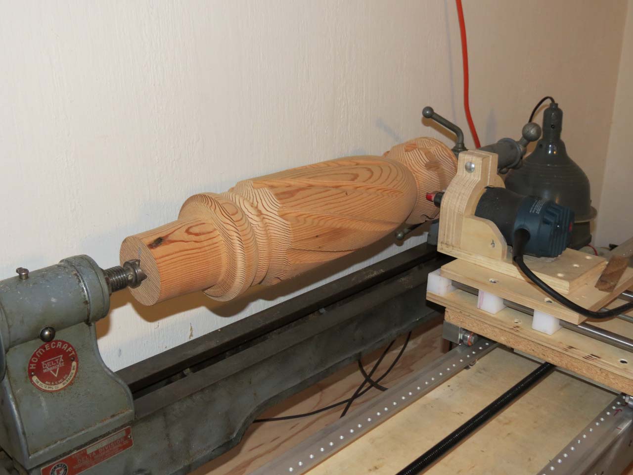
cutting flutes on a big spindle (5" dia, 22" long)
First "real" parts -- the big bolt was fun, but just a test, and a bit of a joke. This is the first "real" part -- a base for a round table (I think). I turned the spindle by hand on the manual wood lathe, and modified the thread code to cut a series of flutes. It worked pretty well, in spite of a couple of errors in the code:
1. I intended to climb cut (feed with the cutter so the bit pulls with the direction of travel. Makes a cleaner cut across grain). This code runs the cutter against the direction of travel (conventional cut), which is more prone to splitting when cutting across the grain.
2. I rotate the part by one degree between the forward and reverse cut in order to make a slightly wider cut. But I didn't account for that when spinning between flutes, so each cut advances one degree around the spindle. I actually like the way it looks, so I didn't fix it, but it was a (happy) mistake.
bottom of x-axis carriage showing new nut and diy tap
Upgraded lead screw. The screw that originally drove the x-axis was a standard hardware store 1/2" x 13 threads per inch rod. It had the advantage of being cheap, easy to work with and with standard threads, easy to connect to. The disadvantage was that it was inaccurate, not straight, and really slow: it took 13 revolutions to travel one inch. I upgraded to an acme lead screw with 5 threads per inch, 2 starts. This gives me faster travel at lower motor RPMs, where they have more torque. It also speeds up the rapid traverse -- it no longer takes a full minute to return the carriage to zero.
The screw was pretty expensive so I just couldn't bring myself to spend another $40 on a nut, and decided to make my own out of UHMW. It only took about 5-6 hours to come up with one that worked... (how cheap do I work? You do the math)
First, I tried to heat form the nut but wasn't happy with the results, so I decided to make a tap and cut the treads instead. I ground a couple of grooves in a length of the acme rod, tapered the ends, made sure that all the thread starts were sharp. Next, a hole was drilled in the UHMW blank a few thou over the thread minor diameter and it was chucked in the metal lathe. With the home brew tap in a chuck in the tail stock, I started the threads by hand. After a few turns, it bound up and started to spin, so I took it out and finished with a vise and a pair of channel lock pliers. That actually worked well because I was able to flex the nut and squeeze the sides in, making the cut deeper. By the time I had gripped the nut by all sides to turn it, it had cut enough clearance to spin fairly freely. Then, I ran the tap back and forth through the nut with a hand drill a few dozen times until it was running smooth. A little teflon lube and it's running smooth with with very little resistance and almost zero backlash.
A couple of observations:
UHMW has a nasty habit of flexing away from the cutter and springing back, so your cuts and holes tend to be undersize.
This approach worked on UHMW because the stuff is so soft and easy to cut. It might work on acetyl, nylon or acrylic, but I doubt it would work so well. My "tap" was very crude -- I think you'd need to make something much more refined to cut a more rigid material.
I left the burr on the cutting edge, so when I was running it back and forth with the drill, it was shredding off a little bit of material with each cut. It did not leave a clean cut, but it helped to overcome UHMW's tendency to cut undersize -- each time through, it removed a little more material.
The first finished part to come off the router lathe. I figured when building a machine to cut big spirals and threads, what better test than to make a great big bolt and a nut to fit on it.
The entire bolt is about 17" long and 3.5" in diameter. The thread pitch is 2.5 threads per inch. The head and the nut are about 6.5" in diameter and the nut is 2.75" thick.
The threads work
The original idea that started this project was to adapt a wood lathe to cut great big wood threads, both internal and external. And here they are. In that regard, I guess I'm finished. However, this project has presented a bunch of new exciting possibilities to explore.
With wrench and screwdriver for scale.
(side note: the wood looks like it has been stained, but it's not. This is its color with neutral Watco oil. The wood was some salvaged asian oak of some kind from shipping containers at the port, and came out much darker than I expected.)