A new CNC has been taking shape in my shop over the last several months. It's a major rebuild of my previous router-lathe that adds another axis of movement and a lot more capability. I kept quiet about it until it was actually running because the design is a little unusual and I wasn't entirely sure if it was going to work -- I wanted to avoid having to say "that new machine I'm building? umm, never mind...".
It's still under construction, but far enough along that I can use it to make parts for itself.
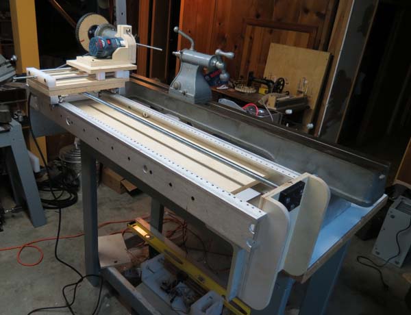
Configured for flat work
Configured for 4th axis (lathe)
It's basically a standard 3-axis router built around an old 11" x 36" wood lathe. It has two configurations: a 3 axis router, or remove the table to access the lathe for 4th axis work. As with previous projects, most of the design work was done in Sketchup before and during construction.
Configured for rotary work on the lathe
With the table installed for flat work.
Here are the first cuts:
Rotary axis test.
The rotary axis (lathe) drive. 16:1 ratio -- kevlar belts.
Here's a wood sign I made for a friend's woodworking shop, Artsubstrates. This is the first time I've wrapped a 3D shape around the rotary axis. It worked better than expected.
(note: from here on is going to be pretty dull for anyone not building a cnc machine. ...and maybe for those who do, as well.)
I generated the text using "FEngrave" a great piece of software for generating gcode for signs. It does one thing and does it very well. Highly recommended. Then I used another piece of software to take the output from FEngrave and wrap it around the rotary axis.
Recent upgrades:
Some upgrades were required to convert from arduino 2 axis
control to 3 axis CNC. Added was new z axis assembly with stepper motor and controller, new belts and pulleys on the rotary axis to increase the
gear ratio, and limit switches on the linear axes.
New Z axis assembly with motor.
The new Z axis assembly has 3/8" aluminum plate for the base and the
carriage platform, 5/8" O1 tool steel rods for rails and UHMW bearings
to slide on. I made another UHMW nut and used the acme threaded rod left over from the X axis. I'll have to re-think the UHMW bearing though -- they slide really smoothly by themselves but take a lot of adjustment to get the carriage to slide without binding with all 4 attached.
Limit switches on Z axis
Motor and switch wiring
Showing the limit switches and motor wiring on the Z axis. I used
ethernet cable and jacks for the limit switches, and heavier 22g wire
for the motor.
New rotary axis belts
The big automobile timing belt and diy pulley were replaced two XL timing belts and pulleys. increases the motor/ axis ratio from the previous 4:1 to 16:1. This provides a lot more holding power against the router and gives smoother rotary axis travel and much finer resolution. With the old belt, there was more backlash that I liked and at larger diameters, one step on the motor translated into as much as .003" of travel. With the new belts and gear reduction, resolution at large diameters is still very fine and I see less chatter during heavy cuts.
The current belts are neoprene with polyester fibers, which do stretch a little and is more noticeable with the double gear reduction. I purchased new belts with kevlar fibers that have very little stretch, but haven't installed them yet.
All this is because these 285 oz/in motors are OK for the two linear axis, but a bit puny
for the rotary axis. A motor upgrade on the rotary axis may be in order,
but would require a bigger power supply and new controller as well -- not in the current budget.
Wiring to the electronics enclosure. 5 pin XLR connectors with 22g stranded cable for the motors and ethernet cable and jacks for the limit switches and e-stop button. There's a vented cover for this enclosure, but after an overheating incident where the cooling fan lost power and the controllers started making real funny noises and smelling bad, I don't have the courage to close it up yet. I'm thinking of putting in a temperature monitor, but that may be overkill.
A lot has happened on the router lathe and this posting is way overdue. It's gained a nice new 3rd axis carriage driven by a stepper motor, adding programmable z-axis (depth of cut) control, and has been converted from arduino control to full CNC, controlled by a PC running Mach3. Here's a video of the first major part cut on the machine since the rebuild.
The conversion to a CNC controller opens up huge potential. The arduino was great for spirals, but it took a lot of code to generate them. I found I could do in 3 0r 4 lines of g code what took 100+ lines of arduino code. I could have installed Grbl and continued using the arduino as the CNC controller, but I like the feedback graphical programs like Mach3 and EMC2 provide. Although I do have an idea for a little internal thread-cutting machine that Grbl might be perfect for.
Cutting the square profile proved to be a bit of a challenge. Unfortunately, on this machine there's no way to move the cutter relative to the center line of the part (bad planning!), so cutting a flat is a little more complicated. After a calling up some forgotten math and doing some sloppy Excel scripting, I was able to make a spreadsheet to generate code to control depth of cut / rotation ratio that generates a flat surface as the part rotates. Then, rotating the part by increments between each cut to produce the spiral was a matter of learning how to use parameters and subroutines in g code to create loops
Here's the Excel function to make the square: =((Offset/COS(angle))+(tool_radius/COS(angle)))-tool_radius
...where offset is the distance from the center of the part to the flat surface you want to generate, angle is the angle relative to the axis of the cutter and tool_radius is... well tool radius. I have a spreadsheet that does all the math and generates g code for different angles and offsets. I'd be happy to share if anyone's interested, but I don't want to post it in its current unfinished state.
A friend gave me some old fir boards torn out of her attic. They were getting in the way where I stacked them in the shop, so I decided to mill them down before storing them. But once I started cutting, I got a little carried away and made a table top to go with the spindle I made in the last post.
The top is a 24" radius quarter round, with the leg centered roughly in the table top.
The curved front apron was made of several thin pieces of stock laminated around a curved fixture and glued.
The tripod base with the legs attached by dovetails. The front two legs are at right angles to each other and the rear leg is much shorter. One major mistake was the thin dovetail web between the front legs, that ended up being a weak point I struggled with later.
It was interesting to build a traditional-looking piece like this. Spindle-turned work always seems to lead in that direction, and in this case, it forced me review some basic skills. It was a good time for that review -- I made a couple of mistakes that could have been avoided if I was a bit more in practice. It was a pretty quick job, and a lot of fun. And it replaces a really ugly folding table in the corner of my living room.
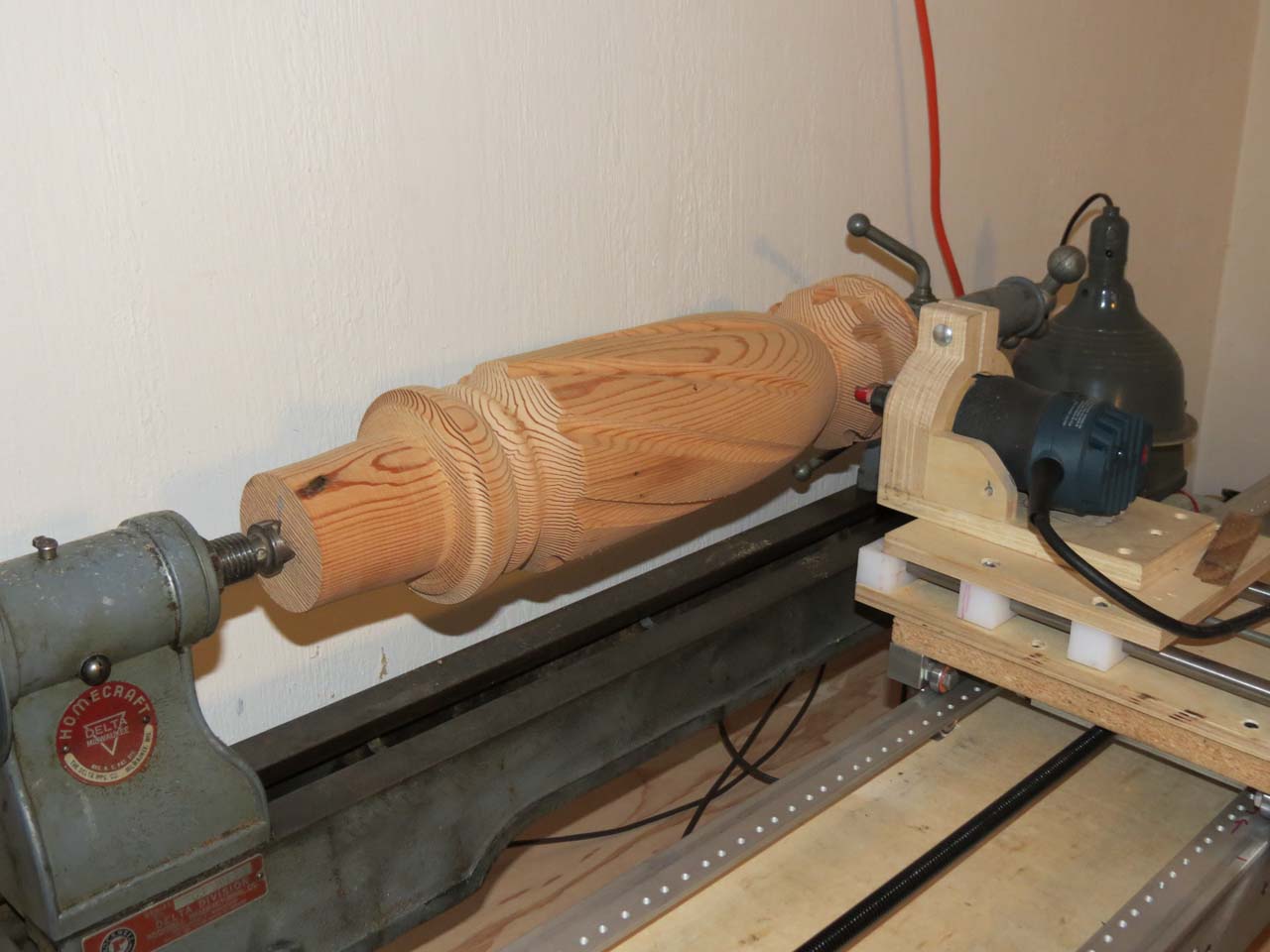
cutting flutes on a big spindle (5" dia, 22" long)
First "real" parts -- the big bolt was fun, but just a test, and a bit of a joke. This is the first "real" part -- a base for a round table (I think). I turned the spindle by hand on the manual wood lathe, and modified the thread code to cut a series of flutes. It worked pretty well, in spite of a couple of errors in the code:
1. I intended to climb cut (feed with the cutter so the bit pulls with the direction of travel. Makes a cleaner cut across grain). This code runs the cutter against the direction of travel (conventional cut), which is more prone to splitting when cutting across the grain.
2. I rotate the part by one degree between the forward and reverse cut in order to make a slightly wider cut. But I didn't account for that when spinning between flutes, so each cut advances one degree around the spindle. I actually like the way it looks, so I didn't fix it, but it was a (happy) mistake.
bottom of x-axis carriage showing new nut and diy tap
Upgraded lead screw. The screw that originally drove the x-axis was a standard hardware store 1/2" x 13 threads per inch rod. It had the advantage of being cheap, easy to work with and with standard threads, easy to connect to. The disadvantage was that it was inaccurate, not straight, and really slow: it took 13 revolutions to travel one inch. I upgraded to an acme lead screw with 5 threads per inch, 2 starts. This gives me faster travel at lower motor RPMs, where they have more torque. It also speeds up the rapid traverse -- it no longer takes a full minute to return the carriage to zero.
The screw was pretty expensive so I just couldn't bring myself to spend another $40 on a nut, and decided to make my own out of UHMW. It only took about 5-6 hours to come up with one that worked... (how cheap do I work? You do the math)
First, I tried to heat form the nut but wasn't happy with the results, so I decided to make a tap and cut the treads instead. I ground a couple of grooves in a length of the acme rod, tapered the ends, made sure that all the thread starts were sharp. Next, a hole was drilled in the UHMW blank a few thou over the thread minor diameter and it was chucked in the metal lathe. With the home brew tap in a chuck in the tail stock, I started the threads by hand. After a few turns, it bound up and started to spin, so I took it out and finished with a vise and a pair of channel lock pliers. That actually worked well because I was able to flex the nut and squeeze the sides in, making the cut deeper. By the time I had gripped the nut by all sides to turn it, it had cut enough clearance to spin fairly freely. Then, I ran the tap back and forth through the nut with a hand drill a few dozen times until it was running smooth. A little teflon lube and it's running smooth with with very little resistance and almost zero backlash.
A couple of observations:
UHMW has a nasty habit of flexing away from the cutter and springing back, so your cuts and holes tend to be undersize.
This approach worked on UHMW because the stuff is so soft and easy to cut. It might work on acetyl, nylon or acrylic, but I doubt it would work so well. My "tap" was very crude -- I think you'd need to make something much more refined to cut a more rigid material.
I left the burr on the cutting edge, so when I was running it back and forth with the drill, it was shredding off a little bit of material with each cut. It did not leave a clean cut, but it helped to overcome UHMW's tendency to cut undersize -- each time through, it removed a little more material.
The first finished part to come off the router lathe. I figured when building a machine to cut big spirals and threads, what better test than to make a great big bolt and a nut to fit on it.
The entire bolt is about 17" long and 3.5" in diameter. The thread pitch is 2.5 threads per inch. The head and the nut are about 6.5" in diameter and the nut is 2.75" thick.
The threads work
The original idea that started this project was to adapt a wood lathe to cut great big wood threads, both internal and external. And here they are. In that regard, I guess I'm finished. However, this project has presented a bunch of new exciting possibilities to explore.
With wrench and screwdriver for scale.
(side note: the wood looks like it has been stained, but it's not. This is its color with neutral Watco oil. The wood was some salvaged asian oak of some kind from shipping containers at the port, and came out much darker than I expected.)
I always knew that the big challenge would be cutting
internal threads. What cutter? How much extension? Speed? How to manage chatter
and deflection? The
criteria was that I wanted to cut threads a half inch deep, at least 3 inches
into a bore. For this I needed a 60 degree side cutting bit that I could extend
3 inches past the end of the router. Good luck finding that router bit…
My solution was to create an offset spindle with a half-inch
shaft that holds a fly cutter. The spindle is made up of a couple of bearings and a .515" ground stainless steel shaft, turned down to a half inch on the ends to fit the bearings. The spindle frame and router clamp is made of birch ply. The spindle is hinged so it can be swung free to check the fit of the bore. The spindle is driven by a vacuum cleaner belt off the router with a 4:1 speed reduction. I bought a cheap Harbor Fright trim router to run it, just in case this is hard on router bearings. (better to trash a $30 tool than a $130 tool). I also got one of their router speed controls to slow it down. (I seem to be buying a lot of cra stuff from those guys lately)
speed control
spindle
.
In order to keep the rotating weight down, I
used 1/4" drill rod for the fly cutter, inserted at an angle through the mandrel, and ground so that
each end only cuts one side of the thread groove.
cutter layout
Grinding the tool bit on my other wood lathe. It was actually much
easier than expected to get the angles and correct extension on the
cutter. The only problem was the drill rod I was using turned out to be
stainless, not heat-treatable tool steel. It holds an edge - kinda.
Grinding the cutter.
To grind the cutter, I slowly spun the lathe spindle by hand while cranking the cross-feed vise back and forth. The cross-feed vise is set at 30 degrees to the cutter. It took a different setup for each end of the cutter. This fixture only ground the angle. All back relief and rake on the cutter were ground by hand & eyeball.
You can hear the harmonic vibration from the stretchy belt, right before the cutter exits the end of the bore. This is a problem I'll have to confront before I can increase depth of cut and cutting speed.
Here's a better video made after the outside of the nut was formed.
Lessons learned:
Needs mass. There's a fair amount of vibration that would probably be dampened by more mass in the router carriage and spindle. I was planning to rebuild anyway after this initial test, I'll just beef things up a bit more.
Stretchy belt -- not so good. I'm getting a significant harmonic vibration, especially when cutting across end-grain that I think comes from belt stretch. (you can hear it in the video, right before the cutter exits the end of the bore) I can dampen it somewhat by putting my finger on the belt. I'll look into a better drive belt to replace the $2.99 Hoover belt I used. More mass in the router carriage may help this as well.
Cutter needs rake. I just ground a flat cutting face on these cutters, so there's zero rake on the cutting edge. I think if they had a little rake ground in they would cut better -- slice the wood rather than scrape.
After spending most of the weekend building a bench for the lathe, a table for the computer and a stand for the air filter, I moved the lathe to its new home. Then I was finally ready to make a big cut as a road test, to test accuracy and speed. I found a 30" long oak 4x4 to use as a test. The lathe can actually handle up to 11" diameter, and about 36" in length, but I figured this was big enough to expose most major problems or weaknesses.
rounding the stock
Everything worked pretty much as expected -- at least the arduino/stepper motor part. No dropped steps -- the cutter followed the exact same path each cut. In my previous test, the pitch was off, but I'm pretty sure it was a loose coupler on the spindle. I did find out that the tailstock is not aligned so the lathe cuts a pretty significant taper, and after 3+ hours of continual operation, my shop vac sounds like squirrels hid nuts in the motor. Once I deal with those issues, I'll start testing how fast and deep it can cut in a single pass.
First threads. They came out looking great, but the pitch is a little off. I found a loose coupler on the spindle motor that I hope is the reason. Otherwise the stepper motor is losing steps or my math is wrong.
Threads look chipped, but that's just the wood grain showing,
the cut itself is very clean.
For electronics, I went with 280 oz, NEMA 23 8 wire hybrid motors, and drivers based on the Sanken SLA7078MPR chip. The power supply puts out 40V and the drivers are configurable up to 3A current. The drivers have step and direction inputs that run great off the Arduino -- just toggle a pin HIGH and immediately back to LOW, followed by a few hundred microseconds delay to control speed. The driver boards also have dip switches to select among full, half, quarter, eighth and sixteenth steps. Mine came set to eighth-step which gives a nice balance between power and smooth motion. Given the low gearing of the lead screw and the 4:1 reduction on the spindle, I'm still experimenting with the best step setting to use on each axis. I may go with quarter or even half step.
There's a 12v/5v switching power supply from a defunct external hard drive zip-tied behind the big transformer, and it breaks out to power the Arduino, the cooling fan and the logic circuit on the stepper drivers. That leaves the big power supply to run only the motors.
12v goes to the Arduino and fan, 5v to the driver boards. I put a diode on the 12v to the Arduino -- when USB was plugged in, but main power off, the computer's USB port was spinning the fan. The diode fixed that and drops the Arduino voltage a bit as well.
I've been pretty happy with the hardware so far, and the initial support was good, however the purchase experience was not fun -- sadly, I just can't recommend the company I bought them from.
More recycled parts...in this temporary build, the aluminum the electronics are mounted to is a shelf from the telecom rack that supplied the base and rails for the lathe.
Here's the feed motor mount and feed screw. The stepper motors are the yellow blocks. The screw is stock 1/2"-13 threaded rod. I picked up a flex coupler at a local surplus store, and put adapters on each end to convert from 1/4" at the motor to 1/2" at the feed screw. the black bearing material the rod runs through is UHMW. It was tough finding a piece of rod that was straight enough. Measuring over 42", the pitch is at least a half thread off (I didn't count, so it could be more than that). My intention is to replace it with 2-start 1/2" acme threaded rod, once the mechanics are all figured out.
Tailstock end of the feed screw using same UHMW bearing.
Spindle drive. My auto mechanic gave me a selection of discarded timing belts. This one's from a Honda, I think. They are huge, but work great. I figured out what the gear circle would be for a 60t gear and drilled holes in a piece of particle board using a rotary table. Then cut & sanded the corners off till it fit. The particle board was just a test, but it works so well, I'll keep using it for now. The black adapter attaching the gear is acetyl turned to fit the spindle.
Spindle motor mount. The small gear is UHMW. This was cut the same as the particle board gear -- close guess on diameter, drilled holes and cut the diameter -- x-acto knife to round the corners. Not terribly pretty, but it runs well with very little backlash or slop. I plan to replace all these "Land of the Giants" parts with much smaller .2" pitch XL belts and pulleys, but this gave me a way to test whether a 4:1 ratio was good without buying a bunch of parts. There's a 5/16" shaft through the small gear and skateboard bearings pressed into the pulley housing, and one end is turned down to 1/4" so a simple coupler could be used to connect it to the motor shaft. This allows the belt to be tight without putting lateral stress on the motor.
(the 5/16" coupler was loose, causing inaccuracies in the first part cut. I thought there was a problem with electronics or code, but so far, all my major mistakes have been mechanical)
First off, I had to see if it would even work. I built a prototype out of acrylic with a rail from an old printer, a couple of little steppers and an Adafruit motor shield. Using a couple of nested loops, I was able to draw all kinds of spiral and geometric patterns on a pvc tube. Here's the code:
I learned a lot. First of which was that none of it could be used on the big machine. The Adafruit motor shield is a great little device and a wonderful learning tool, but it will only handle little motors (600mA). It also has its own Arduino libraries with step, speed and direction commands, that don't translate to bigger drivers that have step and direction inputs. That being said, for small projects, it's a very cool device -- if you're working with motors with Arduino, absolutely get one.
The next thing I learned was what odd devices stepper motors are, and how inconsistent the available data seems until you understand how they work. I'd salvaged steppers out of several old printers, but was never able to make them work. They would miss steps, rattle back and forth, get hot and smell bad. And I was mystified why, when if lucky enough to find a motor with an actual datasheet, it would say something like "2.6 v, 3.4Ohms", but the power supply in the printer it came out of would be putting out 36v, 42v or some other crazy voltage. Huh? (anyone that actually knows something about this may be rolling your eyes right now, but this was all new to me.) I wish I'd found this simple explanation -- it would have saved me lots of time: Stepper motor specs typically give resistance and current values. Voltage, if given, is to calculate current. As long as the current is kept at or below that value, the voltage can increase. A lot. (eye-rollers: please correct me if I got that all wrong, I'm still working on it...) In fact it's assumed that steppers will run at many times the spec'ed voltage. For instance, the steppers I ended up using are rated at 3A, .92Ohms. That comes out to 2.76v. Seems low, right? It is, my power supply puts out 40v, but the driver restricts current to the rated 3A.
The Adafruit motor shield doesn't have current limiting, so you need to use motors that pull less than 600mA. The little NEMA 17 motors at Sparkfun and Adafruit are great for this.
Here's the Sketchup model I used to work out the mechanics. The lathe bed is the angled piece with the t-slot on the right. The two rails on the left are 1.5" x 3" aluminum rails from a discarded telecom equipment rack. The big angle pieces on the bottom are the base of the same rack.
The assembly in the upper left is the feed carriage. The whole unit runs on skateboard bearings by a 1/2"-13 feed screw (not shown in the model, but visible below). On top of that is a z-axis-like router carriage that slides on 1/2" rails, driven by a 1/4"-20 screw to move the router in and out. Stepper motors will rotate the lathe spindle (not shown), and the 1/2"-13 feed screws. The router's depth of cut will be manual, for now at least.
After I got it all assembled, I discovered the angle I used for the base wasn't square, so I
have to shim everything that attaches. Re-using the aluminum network
rack seemed like such a good idea, but I've made a series of compromises in strength, wear and accuracy, in order to use it. Once I get everything figured out, I may rebuild the rails using something better suited.
I found an old lathe at a garage sale and decided to turn it
into a router lathe for cutting spirals, flutes and threads. Initially, I
considered using a strictly mechanical mechanism to synchronize spindle rotation and lateral travel, but after playing with an
Arduino and some stepper motors, I realized that could be a better solution, possibly
even converted to a full CNC system sometime in the future. Now that I know it's going to
work, (I made the first cut today) I'm sharing some notes on the build. I'll be posting over the next few days to get this blog up to where the project is currently.