 |
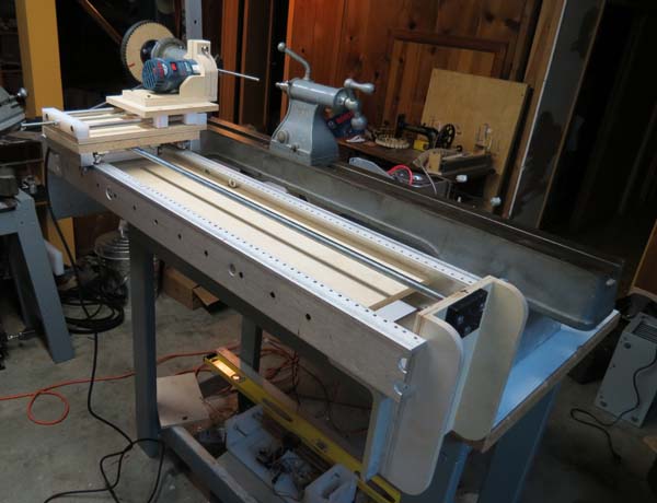
The assembly in the upper left is the feed carriage. The whole unit runs on skateboard bearings by a 1/2"-13 feed screw (not shown in the model, but visible below). On top of that is a z-axis-like router carriage that slides on 1/2" rails, driven by a 1/4"-20 screw to move the router in and out. Stepper motors will rotate the lathe spindle (not shown), and the 1/2"-13 feed screws. The router's depth of cut will be manual, for now at least.
After I got it all assembled, I discovered the angle I used for the base wasn't square, so I have to shim everything that attaches. Re-using the aluminum network rack seemed like such a good idea, but I've made a series of compromises in strength, wear and accuracy, in order to use it. Once I get everything figured out, I may rebuild the rails using something better suited.
Are you still using the 1/4x20 screw for the Z- axis?
ReplyDeleteThanks
No, the rebuilt z axis now has the same 1/2 x 5tpi acme rod as the crossfeed.
ReplyDelete